Stencil Glossary of Terms
An opening in the stencil that corresponds to a land area on the circuit board to be printed.
A set or procedure of rules with recommendations for aperture reductions and modifications in order to optimize stencil design.
Changes in size or shape of stencil apertures in relation to the corresponding landing pad. These changes are designed to improve paste deposition and yield.
The outline of the opening in the stencil, as viewed from squeegee side. Common shapes include rectangles, squares, rounds, ovals and "home plate."
Refers to the width and length dimensions of the opening in the stencil.
The aspect ratio is the ratio of the aperture opening to the stencil thickness. For chemically etched stencils, this ratio should be greater than 1:5. For laser cut stencils it should be greater than 1:2, and for electroformed stencils, which have the best solder paste release characteristics, this ratio should be greater than 1:1. Anything less than these recommended ratios will cause the solder paste to stick into the apertures during release as the retaining force of the paste in the aperture will be stronger than the force pulling the paste out of the aperture.
The relation between the surface of the aperture and the inside surface of the aperture walls in the stencil. The major difference from Aspect Ratio is that Area Ratio is more suitable to shapes, such as circles. Since solder paste has a certain adhesion force, it will stick to the walls of the aperture and to the pad. A pad-to-wall ratio of 0:66 is considered acceptable in our industry. (For example, a 13.5-mm circle in a 5-mm stencil.) See formula.
The angle of the squeegee relative to the stencil surface. The attack angle of the squeegee blade is set mechanically and has a 5° adjustment. For solder printing, the attack angle is normally set to 45° with pressure applied. Most metal blades are manufactured at a 60° angle; therefore, when the default downstop value for the metal blades is applied (0.075"), the blade will deflect close to its 45° angle. Changing the downstop and pressure values, therefore, may cause this angle to change. Most polyurethane blades are manufactured at a 50° angle. The difference in angle between the metal and the polyurethane blade is due to the fact that the metal blades tend to deflect more.
Computer Aided Design and Computer Aided Manufacturing is the general terminology for file types used for computerized design and manufacturing.
This is the least sophisticated manufacturing method of making stencils – a photosensitive process where a negative photo image is used on the metal foil. A double-sided chemical etching process is used to etch the material away in selected areas, resulting in the apertures. The apertures are very smooth but have an hourglass cross-section.
The degree to which the surface of the PCB and the underside surface of the stencil come together. A warped PCB, board surface defects, low profile components and defects, and a damaged or unfinished stencil plate can impact coplanarity.
The average height or depth of the deposited material on the printed circuit board.
Normally a print stroke is set so that there is about a 1" over-travel to either side of the board width. When a print stroke begins, the squeegee travels down to its downstop value (which is a physical stop), pressure is applied and the print cycle commences. If too much downstop is applied, coining of the stencils can occur. Once the downstop comes into contact with the board, the squeegee raises up due to the pressure of the board forcing it up. When printing large boards, it may be necessary to increase the downstop value due to the higher pressure that is needed to get a good print. Holding the downstop in its default value of 0.075" for training edge metal blades, 0.060" for trailing edge polyurethane blades and 0.045" for D-cut polyurethane blades may not be adequate, because no matter how much pressure is applied, the squeegee cannot travel past its downstop value to its 5° angle. Changing the downstop value, therefore, causes this angle to change. Decreasing the downstop value can cause the squeegee to not come in contact with the stencil (the squeegee just makes contact with the stencil when a downstop value of zero is entered) resulting in incomplete prints and insufficient paste on the pads.
Measurement standard used to indicate density or "hardness" of polyurethane squeegee blades (50 is relatively soft and 90+ is harder).
The most sophisticated manufacturing technique of stencils – a photosensitive process where a positive image is used to make a disposable mandrel. Electrolytic plating is used for this additive process where we actually grow the stencil around the apertures. The apertures are very smooth with a very fine resolution.
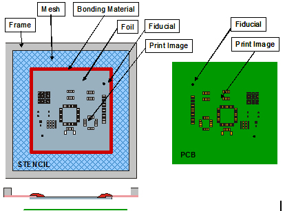
A mark in the artwork that is engraved in the stencil along with the apertures. It is used by the machine vision system to align the stencil to the PCB and to verify artwork orientation and location. Fiducials are laser engraved in either the squeegee side or bottom (board) side of the stencil. "Global" fiducials are located outside the aperture footprint, while "local" fiducials are placed within the image itself, usually in close proximity to an integrated circuit.
Describes the layer of the PCB that the Gerber information represents. The solder paste layer is a 1:1 reflection of the component lands on the board.
Stencils are usually secured to an aluminum frame with a tightly stretched mesh border. Alternatively, a stencil can have mounting holes etched along the perimeter for temporary mounting on a universal-sized frame, such as the VectorGuard frame or competing frameless systems. The user requires typically one frame per printer and buys foils with only the stencil image made in the foil. This foil then gets tensioned into the reusable frame.
The size of the frame for mounting stencils is determined by the screen printer model. The smaller cast-aluminum frames are usually specified by the inside dimension (ID), e.g., 12" x 17" or 20" x 20". Tubular aluminum frames are usually specified by the outside dimensions (OD), e.g., 29" x 29".
The degree to which a stencil aperture contacts and "seals" against a landing pad. Good gasketing decreases solder "squeeze balls," which is random solder balling and bridging.
Standardized PCB design language and operating commands which ultimately define the slope and location of apertures in a stencil plate.
The conductive area on a PCB to which components or separate circuits are attached.
The most popular manufacturing technique for current stencil technology. The CAD/CAM file is used directly to generate a CNC-file that drives the X-Y driven laser head. The laser will cut the perimeters of the apertures, resulting in tapered apertures. The wall structure is rougher than the other techniques due to the "melting" effect of the laser beam.
An Electroforming process to make the hard nickel blanks, followed by laser cutting of the apertures with a high precision, frequently calibrated stencil laser. Nickel stencils are perfect for prototyping as well as medium- to high-volume print runs featuring medium aperture counts.
The stencil is slightly above and not in contact with the board during the print cycle.
The stencil is in contact with the board during the print cycle.
The actual area of the pad covered with adhesive paste.
Laser imaging of Gerber data onto film. The resultant photopositives are used for chemically etching stencil plates.
The print speed parameter field controls the speed that the squeegee travels across the stencil surface. If the squeegee profile is activated, this field will display "profile" and will not be adjustable. A good start setting for squeegee speed is 1 inch/sec (depending on paste being used). Increasing the squeegee speed too much can cause the aperture to be inadequately filled, especially apertures perpendicular to the direction of travel of the squeegee. Using a slow squeegee speed allows time for the paste to fill the apertures, resulting in complete/well-defined points.
The return to normal of a stencil after being deflected by the squeegee moving across the surface of a stencil and substrate. Snap-off is the distance between the top of the board and the bottom of the stencil during the print stroke. The positive snap-off value is the space between the board and the stencil. Negative snap-off is the actual deflection of the board onto the stencil. Zero value indicates that the board is just contacting the stencil. For the majority of stencil print applications, on-contact printing is the most desirable. This tends to give more uniform paste heights across the board. Snap-off would be mainly in printing hybrid circuits, such as ceramic substrates using a wire mesh to screen ink/paste. Here, a snap-off is needed to release the ink/solder paste from the wires in the mesh that make up the screen. Snap-off may also be used if printing cycle time is to be reduced. Instead of using the slow snap-off feature found on many printers to ease the paste out of the apertures, a snap-off can be input, and once the print cycle is complete, the Z tower can drop to unload height. Snap-off gives an indirect "peel-off" of the board from the stencil. The disadvantage of using a snap-off with stencil printing is that the prints of fine pitch devices or the leading edge of the pad may have "dog ear" (a little spike of solder paste), giving rise to inconsistent paste volume (this depends on the paste printing characteristics).
The height the stencil is set above the board for an off-contact printing, which determines the amount of snap-back action of the stencil. On-contact printing would have a zero snap-off distance.
A 1:1 reflection of the component lands on the board.
A rubber or metal blade wiped across the stencil to force the material through the apertures onto the PCB. Metal blades are generally preferred for fine pitch printing and where rubber blades pump or scoop material through the apertures.
The Total Force is the amount of force that the squeegee blade applies to the stencil during the print cycle. The correct squeegee length to be used is determined by the length of the aperture image. Use a squeegee length that is equal to the length of the image + 2" (1" clearance on either side). This reduces the effect of unnecessary force being applied to the squeegee and stencil during printing. A good start setting for squeegee pressure is 1-1.5 pounds of pressure per inch of squeegee. Use only enough pressure to get a clean wipe on the stencil to get a good quality print. Applying too much pressure to the stencil can cause the squeegee to "dig" into the apertures and scoop paste out (if using the polyurethane blades). If using metal blades, this scooping effect is less likely to occur, due to the fact that the blades are of a harder material and are, therefore, less likely to conform to the shape of the aperture. Ideally, the squeegee blades should be at a 45° angle (when pressure is applied). This allows for equal force to be applied in the vertical and horizontal directions as the squeegee travels across the stencil. There are some cases where a greater angle is required than the normal 45°. One of these cases is when printing thru-hole devices. Normally when printing thru-hole devices, a thicker stencil is required. In order to get the required volume of paste onto the pad and into the thru-hole, it may be necessary to increase the pressure on the squeegee blades in order to achieve a greater attack angle, thus allowing greater force in the vertical direction. Increased squeegee pressure can also lead to the solder paste bleeding underneath the stencil, leading to shorts. Decreasing the pressure or having insufficient pressure will result in incomplete prints and insufficient paste on the pads.
A sheet of metal with apertures used to deposit solder pastes or adhesives in specific locations on a PCB. The most common material for stencils is stainless steel.
Repeating a single Gerber file over two or more areas of the same stencil plate. PCBs are arranged on "breakaway" panels often referred to as 2 Up, 4 Up, etc. Information on the center-to-center dimensions is essential to prevent mis-registration of panel to stencil.
Reduction or increase of stencil thickness in specific areas of a stencil on either the top or bottom side(s). Step Up refers to an area higher/thicker than the majority of the stencil; Step Down refers to an area lower/thinner than the majority of the stencil. Used to control paste deposits on PCBs with both standard pitch and fine pitch components. Also used for creating an underside cavity to accommodate surface circuitry, vias or other low profile surface components in order to optimize stencil gasketing.
This field set to the plus (toward the rear of the printer) and the minus (toward the front of the printer) travel limits of the squeegee. The recommended squeegee stroke distance should typically be 1" past the stencil apertures at either end. Larger squeegee strokes may be used if printing higher viscosity/difficult to print pastes in order to give the paste more time to start its rolling effect and to knead the paste prior to reaching the apertures.